Plik:Diesel engine schematic.png
Diesel_engine_schematic.png (250 × 310 pikseli, rozmiar pliku: 20 KB, typ MIME: image/png)
Opis
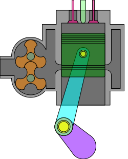
Opis English: Cutaway schematic of a uniflow diesel engine. On the left is a Roots-type lobe blower, which provides positive pressure downstream (to the right) into an air chamber which surrounds the engine cylinder. As the piston travels down, it uncovers the side ports, drawing air into the cylinder; as the piston travels back up, the air is compressed and heated. At or near the top of the stroke, atomized diesel fuel is injected into the compressed air, causing it to ignite and drive the piston downward; shortly after ignition, the pink exhaust valves on top of the cylinder open to allow exhaust gases to exit; this is aided by the inflow of air from the air chamber as the piston reaches the bottom of its downward stroke.
Data 11 czerwca 2024
Źródło Wikimedia Commons https://commons.wikimedia.org/wiki/File:Uniflow_2-stroke_diesel_static.svg
Autor Mliu92
Historia pliku
Kliknij na datę/czas, aby zobaczyć, jak plik wyglądał w tym czasie.
| Data i czas | Miniatura | Wymiary | Użytkownik | Opis | |
|---|---|---|---|---|---|
| aktualny | 17:36, 21 mar 2026 | | 250 × 310 (20 KB) | Admin Kolejopedia (dyskusja | edycje) | Opis English: Cutaway schematic of a uniflow diesel engine. On the left is a Roots-type lobe blower, which provides positive pressure downstream (to the right) into an air chamber which surrounds the engine cylinder. As the piston travels down, it uncovers the side ports, drawing air into the cylinder; as the piston travels back up, the air is compressed and heated. At or near the top of the stroke, atomized diesel fuel is injected into the compressed air, causing it to ignite and drive the pi… |
Nie możesz nadpisać tego pliku.
Lokalne wykorzystanie pliku
Poniższa strona korzysta z tego pliku: